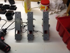
I measured up the G25 pedals and they were all good to fit, so I modded the brake pedal with a better spring force and set them aside for install later. I still needed to figure out if I was going to invert them or not and how to make them adjustable.
clean up the Traffolyte dash, fit the original G25 PCB under the FFB motors, mount the original connector harnesses to allow the pedals and shifter to be plugged in without modification and finish off the paddle shifter arrangement.
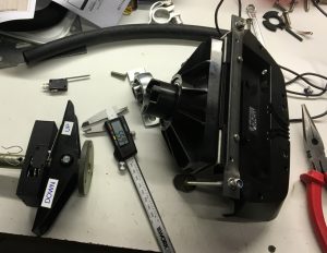
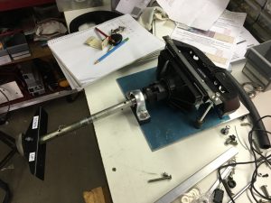
I devised a plan to mate the original steering shaft with the G25 without modifying either part, not that I really cared if I hacked up the G25 but with some careful consideration there was no need to hack anything. Except the G25 housing. The G25 housing forms part of the working mechanism so I removed excess parts and just kept the bits I needed.
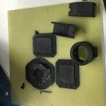
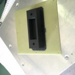
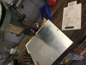
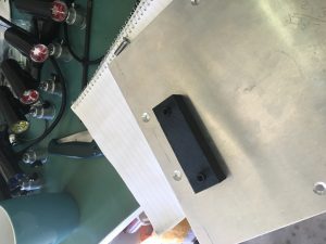
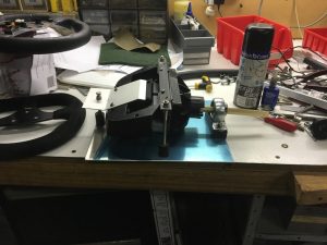
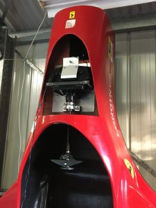
The G25 installation was going to take some time and more experimentation so I fiddled and fit and re-fiddled and re-fit numerous times, eventually coming up with the G25 innards, inverted, coupled and mounted onto a flat plate that I could fit up before installation. This meant I could make adjustments and alignments on the bench and get everything just right before fitting, and it would make removal for service easier if required. There were various 3D printed parts required. This process took the biggest portion of time but the results are great; G25 guts mounted on rubber shock mounts to prevent noise being transferred through the wooden ‘firewall’, adjustable for fine-tuning the alignment, the original steering shaft run through proper bearings and nothing protruding above the natural line of the nose section. Tick.
These things also required some 3D printed parts.
Then I pulled it all out again so I could carry on with lots of other bits and pieces.
Read More: Lots of bits and pieces
